During my recent relocation there wasn’t much time to create my usual Monday web updates. I tried to post short updates on instagram if I could, although with the move, even that was difficult. Progress was sparse, but I did manage to get some work done over the last few months, even with a the shop out of commission.
Now to catch this blog up. If you’re following me on Instagram you’ve already seen many of these photos. This one won’t be as thorough as I’d like but it’ll give you an idea of what I’ve been up to.
When I left off back in August I’d done a post called “Rhino”. This showed the CAD work that I’d prepped so that I could get a lot of the parts cut out. This first picture shows the freshly cut out parts. You can see that at this point the new shop was still being set up. The good new was that all the parts lined up perfectly and were ready to be assembled.

The first thing assembled was the panels for the numbers that fan out around the main dial of the clock. I started with a permanent marker to get a rough idea of where I thought the screws would look best. Then I used calipers to more accurately measure those positions. Next it was off to the mill to drill and tap all the tiny 0-80 threads. Finally I spent some time on the lathe making the little screws to hold everything together. I usually vary the screw head sizes to make things more visually interesting.


Another part of the clock that I finished was drilling the holes for the front two plates of the clock-frame and making the pillars that hold those plates together. This process seems pretty simple, but it’s actually one of the more stressful parts of the whole clockmaking process. Those holes hold the gear arbors, and the gears need to be exactly the right distance apart or the clock won’t run efficiently (if at all).

Lots of scribbling on the brass plates to make sure I don’t put a pillar where any of the components are.

Using a reamer to put a nicer, more accurate finish on the plate-holes.

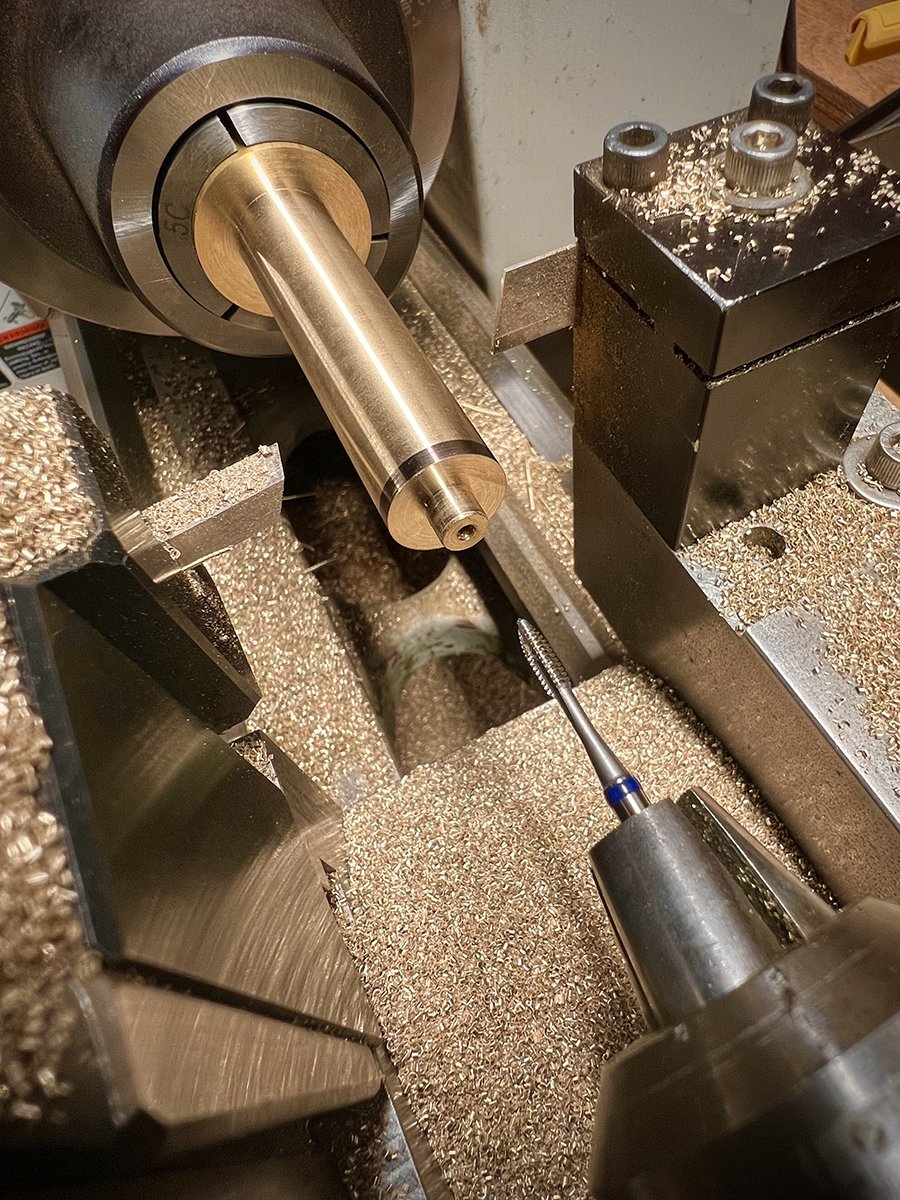
Using the lathe to turn a spigot that matches the plate holes, then tapping 1/4-20 threads.

Threading 1/4-20 screws.

Pillars and screws - Threaded and tapped.

The front two plates. Assembled and ready for gears.
The most recent thing that I finished was the pillars and bridges that hold the parts for the perpetual calendar mechanism. Just like the clock frame, this was a delicate and stressful process because the distance between the holes was so crucial. Maybe even more so with this mechanism, since the gears and levers being held by these bridges are even smaller, with tighter tolerances.
I’ll note that these pillars are slightly different than the clock frame pillars. The ones for the main clock frame are simply bolted from both sides. But for these I couldn’t do that because the moon would run into the bolts if they stick out from the back even a little. For that reason I had to put a big flange at the base of each pillar and screw it from the front. Each pillar still has a spigot on the back to help with alignment, but it doesn’t extend past the 1/4 inch plate.
All the bridges were cut out by hand with a jewelers saw.
I’ve tested everything out and it looks like the bridges came out perfect. It’s great to see these parts moving on the actual clock frame (previously they were only on plastic test-plates).
I’ll show the whole perpetual mechanism in place in the next post.

Using an extra long drill bit so the chuck clears the pillars.

The completed bridges for the perpetual calendar mechanism.