Biggest Gear Finished

The biggest gear for the new clock is finally finished. This one took a lot out of me! Half-inch brass means some pretty heavy cutting and grinding to bring this part to it’s final form. I’m happy it’s finished and I’m very satisfied with the results. 

Next step is the steel arbor with the square winding key. Once that’s done I’ll know how thick this whole assembly is and I’ll be able to add the back plate of the clock frame. Then I’ll make the escapement and get this thing ticking…soon…eventually. Patience.

Big Gear Progress

Barrel assembly:

Most weight driven clocks use a cylindrical drum that a line winds around. A weight pulls on that line, turning the drum, which turns the first gear in the gear-train. There’s also typically a click-and-ratchet assembly so that when the weight gets close to the floor, and the drum is almost out of line, you can wind the weight back up to the top while the gear stays put.

During the winding process the weight isn’t delivering power to the clock, so the clock temporarily stops. If you want the clock to keep ticking during winding you’ll have to add a “maintaining power” assembly. This video gives you an idea of what that consists of.

The larger ratchet will be engaged by a click that’s attached to the clock frame. The torsion spring on the inside gets loaded up by the pull of the weight. Then, during winding, when the barrel and small ratchet are turning clockwise, the large ratchet holds firm, and the spring keeps pushing the clock-train forward. Power is maintained, and the clock doesn’t miss a beat.

Spoking the great wheel:

The largest wheel of this clock is made of 1/2 inch brass. It’s transmitting the most amount of force, so the teeth need to be thick so that it doesn’t wear out too fast. The spokes of this gear needed to be cut out with a simple hand-held jewelers-saw. This took awhile, but it’s finished now, and I’m on to the more fun task of sculpting those gear-spokes with a rotary tool. 

Complications finished

I’ve finished all the complications aside from the sculpting and finish. This includes the day, date,  month, & moon dial. It also includes a drag-fan mechanism that makes everything move soft and slow.

I’ve been testing everything out and it seems to be working really well. It’s always a great feeling to go from plans to a fully-functional mechanism without any major mistakes or oversights. Sometimes it’s tricky to figure out all the overlapping layers, levers, and bridges. I’m always worried I’ll accidentally put a pillar where a lever needs to swing, or a gear where an arbor needs to go through.

The next step is to finish the main clock train and get this clock ticking. To do that I’ll have to finish the escapement, and the barrel assembly for the weight wheel. Both of those jobs are pretty time consuming, but I’m hoping to hear ticking by the end of January.

Weekly Update

Lots of progress this week, although a lot of it will be difficult to show since the clock is still in pieces. The new additions to the clock include two gears, two pinions, a post for the 24 tooth ratchet click, a pillar for the large bridge, redoing one of the bridges for the perpetual mechanism, and a handful of other odds and ends.

The biggest accomplishment for me was redoing one of the bridge for the perpetual mechanism. This is shown in the pair of photos with “New” and “Old”. I’ll explain the need for the updated version, but as I said, this one will be difficult to understand without seeing the gears in it. The old version housed one gear. The gear it meshes with came out of the center-hole nearby, and was cantilevered on an 1/8” steel arbor. When I had the clock together I felt that the gear was cantilevered out way to far, and the arbor needed support on the other end. Especially because another gear and both hands for the perpetual display would need to be added to the end of that arbor over three inches out. I decided to make the pillars taller, and recut the bridge to include a hole that will house the center gear too.

So here’s what makes machining that part tricky. Normally the holes for the bridge and the backplate are drilled at the same time ensure that all the holes line up perfectly. This wasn’t an option since the holes on the backplate are already drilled, and I didn’t want to mess with them for fear of ruining the finish or shape of them. Getting the holes on the new pillars and bridge to line up with the old ones required a lot of very careful measuring and patience. 

I also cut my first gears and pinions in the new shop. This includes the big 180 tooth gear that will turn the four moons. The setup is working well, which means it’s official…I’m fully operational in the new space. 

One of the other little parts that I included a couple pictures of is the post for the 24 tooth ratchet click. I like how the base has that cutout that wraps around the nearby pillar.

Sooo much left to do but i’m slowly getting there. This week will be a little short due to the holidays, but things are definitely set up in the new space and everything is in full swing now. I’m looking forward to pouring in the hours in the new year.

Gear Balancing

Gear balancing time. 

Balancing the gears of a clock is crucial. The power needed to drive the gears should be constant. If the gears aren’t balanced then the required power will fluctuate from very little to a damagingly large amount.

When the gears are visually asymmetrical, as mine almost always are, I have to balance them by shaving metal off the back (unseen) side until the weight is balanced. To check this I put the gear on an arbor that’s spinning on precision bearings. When I can stop it in all positions without it turning on it’s own I’m good to go. This involves a lot of back and forth between checking the balance and grinding a little more until it’s just right. If I accidentally remove too much it can be a problem, so it’s best to go slow.

Big Update

During my recent relocation there wasn’t much time to create my usual Monday web updates. I tried to post short updates on instagram if I could, although with the move, even that was difficult. Progress was sparse, but I did manage to get some work done over the last few months, even with a  the shop out of commission. 

Now to catch this blog up. If you’re following me on Instagram you’ve already seen many of these photos. This one won’t be as thorough as I’d like but it’ll give you an idea of what I’ve been up to.

When I left off back in August I’d done a post called “Rhino”. This showed the CAD work that I’d prepped so that I could get a lot of the parts cut out. This first picture shows the freshly cut out parts. You can see that at this point the new shop was still being set up. The good new was that all the parts lined up perfectly and were ready to be assembled.

The first thing assembled was the panels for the numbers that fan out around the main dial of the clock. I started with a permanent marker to get a rough idea of where I thought the screws would look best. Then I used calipers to more accurately measure those positions. Next it was off to the mill to drill and tap all the tiny 0-80 threads. Finally I spent some time on the lathe making the little screws to hold everything together. I usually vary the screw head sizes to make things more visually interesting.

Another part of the clock that I finished was drilling the holes for the front two plates of the clock-frame and making the pillars that hold those plates together. This process seems pretty simple, but it’s actually one of the more stressful parts of the whole clockmaking process. Those holes hold the gear arbors, and the gears need to be exactly the right distance apart or the clock won’t run efficiently (if at all).

Lots of scribbling on the brass plates to make sure I don’t put a pillar where any of the components are.

Using a reamer to put a nicer, more accurate finish on the plate-holes.

Using the lathe to turn a spigot that matches the plate holes, then tapping 1/4-20 threads.

Threading 1/4-20 screws.

Pillars and screws - Threaded and tapped.

The front two plates. Assembled and ready for gears.

The most recent thing that I finished was the pillars and bridges that hold the parts for the perpetual calendar mechanism. Just like the clock frame, this was a delicate and stressful process because the distance between the holes was so crucial. Maybe even more so with this mechanism, since the gears and levers being held by these bridges are even smaller, with tighter tolerances.

I’ll note that these pillars are slightly different than the clock frame pillars. The ones for the main clock frame are simply bolted from both sides. But for these I couldn’t do that because the moon would run into the bolts if they stick out from the back even a little. For that reason I had to put a big flange at the base of each pillar and screw it from the front. Each pillar still has a spigot on the back to help with alignment, but it doesn’t extend past the 1/4 inch plate.

All the bridges were cut out by hand with a jewelers saw.

I’ve tested everything out and it looks like the bridges came out perfect. It’s great to see these parts moving on the actual clock frame (previously they were only on plastic test-plates).

I’ll show the whole perpetual mechanism in place in the next post.

Using an extra long drill bit so the chuck clears the pillars.

The completed bridges for the perpetual calendar mechanism.

It's been awhile!

It’s been almost three months since my last update. I’ve been putting up some progress posts on instagram, however even that has been a little sparse lately. The reason? I’ve moved!


My projects are growing and the need for more space could no longer be ignored. After a lot of house hunting (like, an exhausting amount) I finally found something that perfectly fits the needs of my increasingly ambitious clockwork projects.


It’s been quite an ordeal. Moving is a huge interruption under normal circumstances. Hunting down a new house, selling the old house, the loans and legal stuff, and then there’s packing up and moving everything that I’ve accumulated over the last 18 years in my old space. But the really difficult part was relocating the shop. I have some big and heavy machines, and here’s the thing: The industrial moving companies didn’t want to bother with a small residential move, and the regular moving companies didn’t have the ability to move the heavy stuff safely.


Sometimes you just have to figure things out for yourself. Below are some links to the move that I posted on instagram. I’d post the files directly, but I unfortunately lost my phone right in the middle of the move, and it wasn’t backed up (brutal).


https://www.instagram.com/p/CiSyBRhL-2M/?igshid=MDJmNzVkMjY%3D


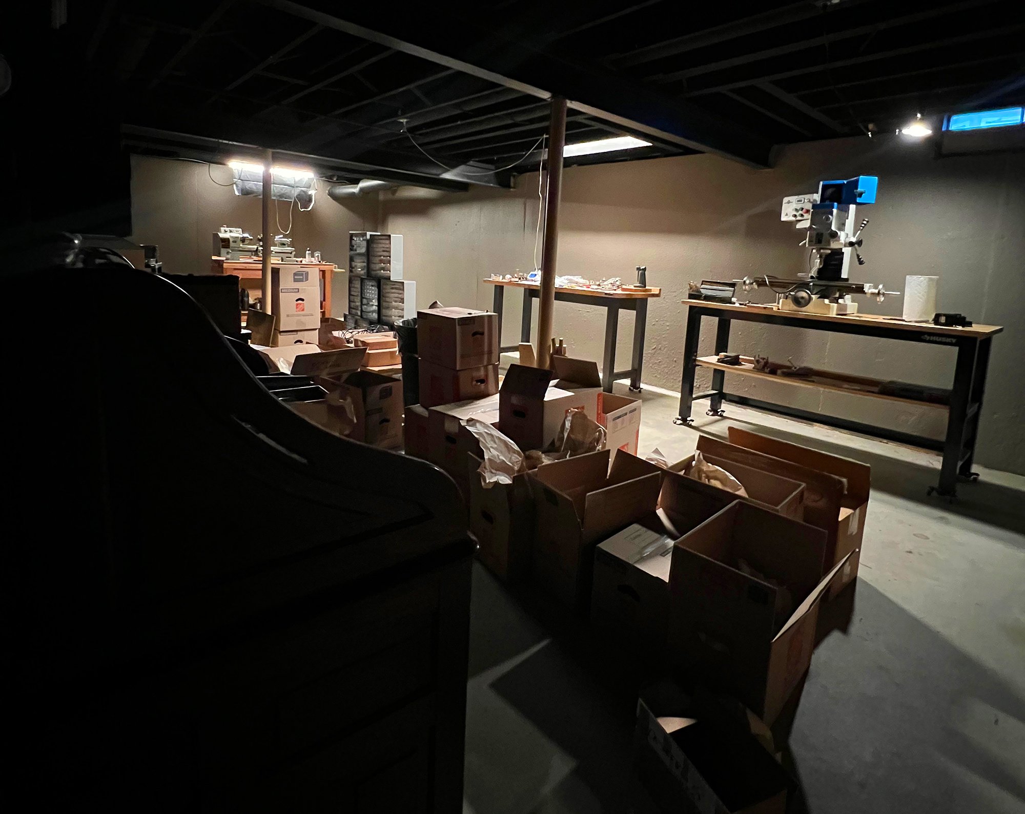
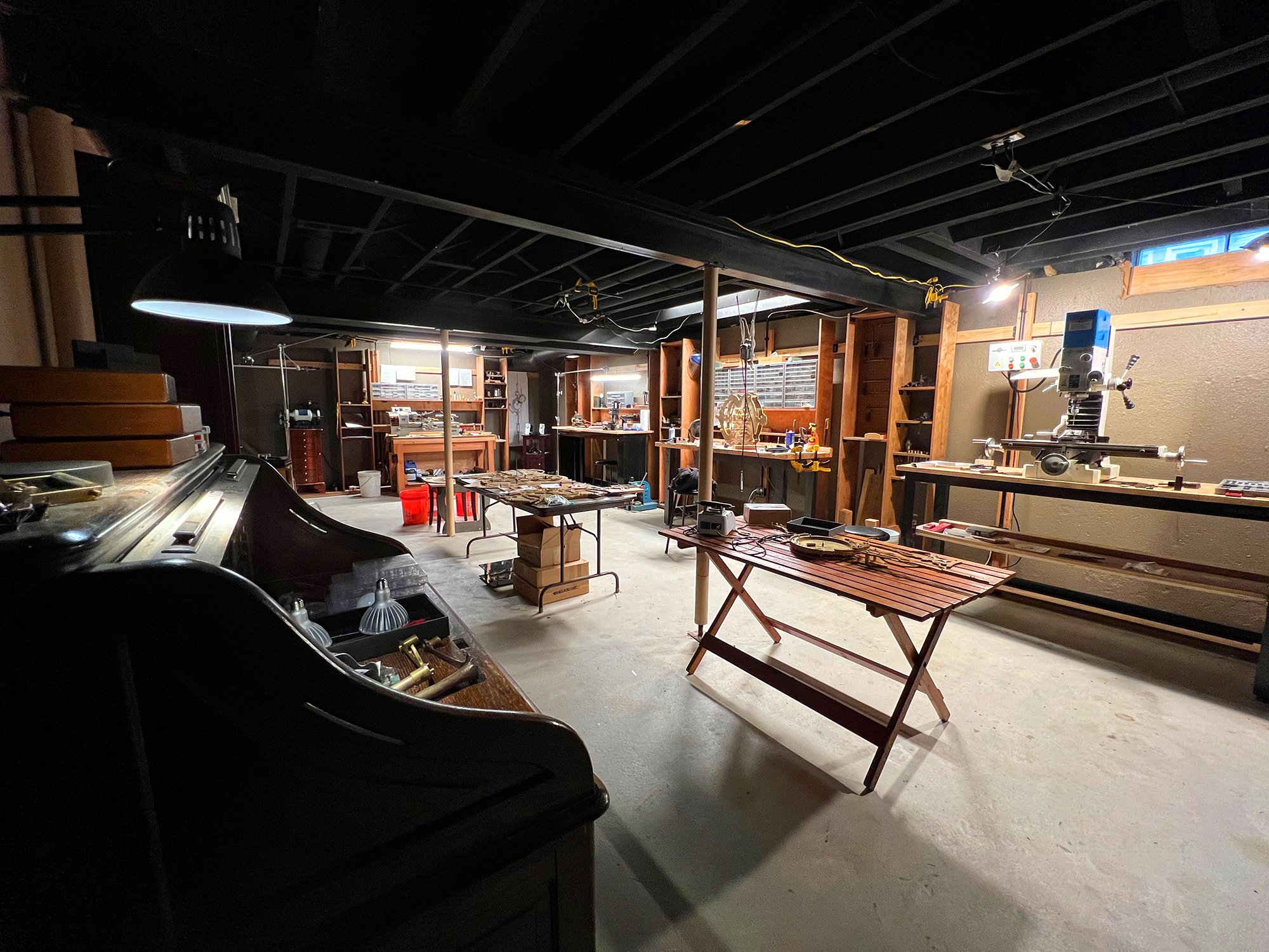
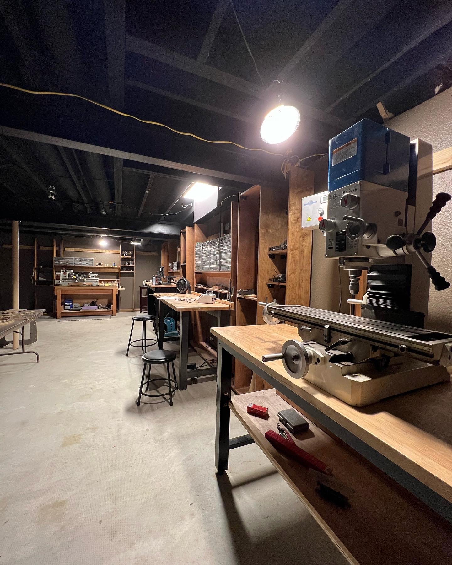
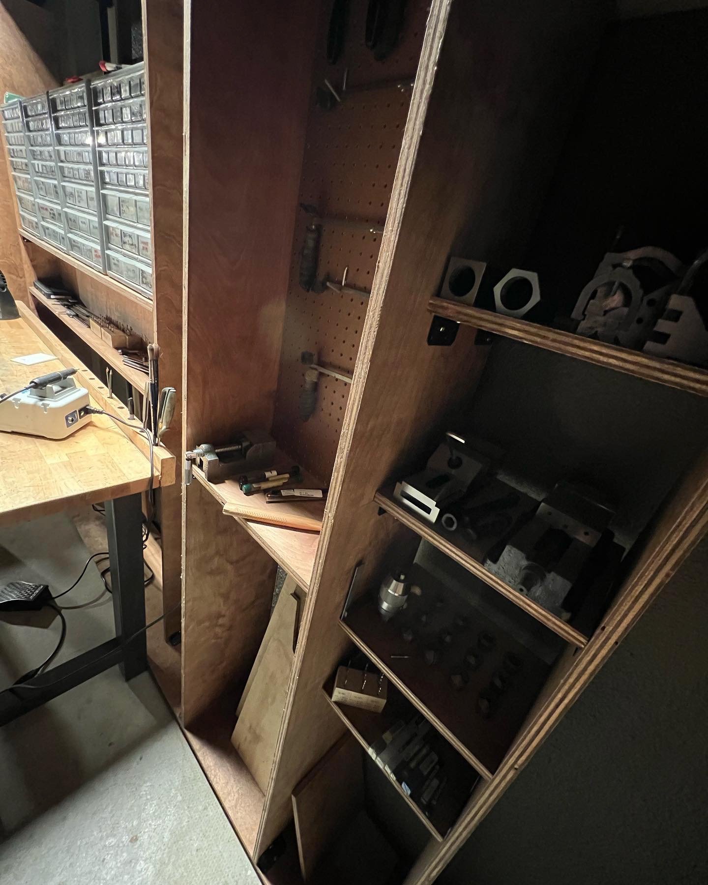
After everything was moved I had to do quite a bit of work on the new space. This included wiring up lots of outlets (both the garage and basement only had one each!?!) Wiring a couple of 220v outlets for the big mill and lathe, and wiring the 3-phase converter for the mill. Ripping out the carpet in the basement and building lots of shelves so that I have a place to put everything. And finally, installing decent lighting.


Here are a few photos of the new space. I had pics of the whole transformation but again….lost phone. The “before” picture is actually from the original listing of the house. The stuff isn’t mine, but you can see what the space was before I changed everything.


There’s still a lot I want to do to the space, but it’s to a point where I can get back to work. There have been enough delays. It’s time to make some clocks.


I’ll post more within the next couple of days to catch this blog up on the clock progress. I’ve been happily working in the new space for over a month now & I’m approaching the really fun parts of the project.

Apologies for the long absence. Thank you for your patience. Stay tuned!

Rhinoceros

Time for some computer aided design - emphasis on the design. My CAD program of choice is Rhinoceros, thus the title.

I’ve changed my tune quite a bit over the years when it comes to using CAD to create my work with automated machines. I’ve arrived at the conclusion that as long as my pencil and brain are steering the ship it’s a very valuable tool.

In the past my hangup with using computers was that the tools in the CAD program start to dictate and influence the look of things, often making them overly perfect and lifeless. But if you can bring your pencil drawings into the program with all of their character, and perfectly trace those imperfect lines, then you can get the best of both worlds.

It’s also important to mention that my commissions crossed a size threshold that made it impossible to fabricate them by hand. This one is no exception, being 6 feet wide and cut from thick 1/4” plates.

One note: I’ve just realized that before I can finish this I’ll have to make the biggest gear in the clock. The spot where the winding key for the weight will be needs to be exact, and I won’t know that placement until I have the gear to physically mesh it with the pinion and get the precise distance between the arbors. While I can certainly calculate that distance with the math, it’s more accurate to physically mesh the gear and pinion together and measure the distance.

Also, I’m moving soon! Pretty soon all of my content will be shot in a new shop. Can’t wait!

Perpetual mechanism first clicks

I’ve just finished carving and balancing the scissor style levers that control the perpetual calendar dates. I’ve tried to film and edit this video in a way that shows how these mechanisms work. I’ll give a quick explanation as well, but if I’m being honest, I’m having difficulty concisely explaining this one with words.

The lever that I’m moving in the video will actually be lifted and released once a day by the snail-cam. It’s always lifted the same amount. The other lever that pivots with it moves until the notched wheel (calendar wheel) stops it. The calendar wheel has 48 positions - one for each month over a four year period. The depth of the notches on the calendar wheel correlate with the amount of days in each month.

At the right end of the lever you’ll see two clicks moving around a shark-toothed wheel. The bottom click moves the wheel forward one tooth a day. The top click only engages at the end of the month, when it will reach back, drop into the notch, and move the shark-toothed wheel in concert with the bottom click. How far it reaches back is governed by the notches in the calendar wheel. The further it reaches back, the fewer days it will take until it drops into place, and the more “extra days” it will grab as the lever travels back to it’s starting position.  

The end of the video shows what happens at the end of the month of February, when the deepest notch is used, and the shark-tooth wheel is advanced four clicks/days.

For any clockmakers out there, I wanted to note that the shark-tooth wheel and the one it meshes with are depthed a little far apart, which is why the one wheel jiggles a little after it’s moved each click. Something that will be adjusted when I put this mechanism into it’s final clock frame.

Balance

The plan was to get the perpetual calendar mechanism working before I started carving and finishing the various pieces. However as I started to test things I realized that I can’t get the mechanism working unless I balance the wheels.

The reason is that there are two clicks that hold those wheels in place while the rest of the mechanism moves around throughout the day. If the wheels aren’t balanced the clicks need to be stronger (heavier) to keep the wheels from moving on their own. And if the clicks are heavier entirely too much force is required to move the wheels forward at the end of the day.

Before I could balance the wheels I needed to sculpt them to their final shape. Then was just a matter of spinning them to see what side was heavy, and carving away metal on the back (unseen) side until they were balanced. I included a photo of the back of the calendar wheel showing the area that I carved away.

Now that these three parts are balanced there barely needs to be any weight behind the clicks to keep everything in place. At the end of each day the mechanism can be bumped forward one tooth with very little effort. Nice and smooth:)

Slowly getting there

So progress has been at a snails pace lately for a couple of reasons. Firstly, this part of the process is always full of lots of trial and error, recuts, and tweaking the geometry. This is especially true of the calendar part of the mechanism, because there are multiple interconnected components that all affect each other. Change one thing and the rest might be off too, so there’s a sort of delicate balance to achieve in the relationship between many of these parts. Especially the perpetual-calendar part of the mechanism.

That part is getting close. It looks rough right now, but once the geometry is working I get to start carving. And that’s when the real fun begins!

The other reason for my slowed pace is (announcement time) I’m going to be moving soon! My projects are growing and so must the space I use to create them. The process of both finding a space that can accommodate my unique needs, and getting my current house ready to sell is very time consuming. However once the move is finished workflow will increase. It’s sort of a short term delay that will make things faster and more enjoyable in the long run.

Moving is always a pain, but moving all of my heavy equipment will be…well, I don’t want to think about it yet, but it’s gonna be brutal.

Working on this clock is always the bright spot amongst the chaos. More soon!

First clicks

Testing the first two mechanisms for the latest clockwork commission.

The snail cam that you can see me turning at the beginning of the video is the arbor where the hands will be. The lever that this cam lifts and drops operates everything except the time, so it’s a little heavier. That means there would be a lot of friction if I were to use a regular lever and cam, so I wanted to use a bearing instead.

Since bearings are round and I needed it to drop sharply as if it were a point, I had to employ a “slip cam”. If you look you’ll see a pin which is actually pushing the cam from inside a slot. Once the center of the bearing is over the edge of the cam it falls, and nudges the cam forward without disrupting the arbor that turns the hands of the clock. Then the arbor keeps moving forward, and the pin picks up the cam again when it ticks its way back to the front of the slot.

That cam turns once an hour. The long lever clicks a ratchet that has 24 teeth (one for each hour of the day). That ratchet will have multiple cams, each one activating another thing that needs to change at midnight.

The end of this video shows one of those cams dropping at midnight. This one is clicking a 7 tooth star wheel, which as you can guess, is for the days of the week. In order to make that 7 tooth star move precisely there are actually three components working in concert. The click at the end of the lever that pushes it, the back side of that same click which stops the wheel from moving forward past one day, and the pawl at the top that holds the star in place while the lever cocks back for the next day. Getting the geometry just right was a little tricky for me, but I like the way it came out. The star moves abruptly and stops sharply without any slop. That sharp click could also be achieved with a jumper spring, but this way requires less force, so it’s much more efficient. 

Next I’ll be adding the perpetual calendar levers (I think)

Test Frame

Since the last post I’ve made a handful of pinions, spoked out the snail cams for balance, and made the little star wheel for the day click.

There were also a couple of other things that required more time than expected. I put some of the clicks and levers on a test plate (a clockmakers depthing tool actually) to check the functionality and geometry. A couple of them were a little on the fussy side. I prefer things to work with absolute certainty, in a way that can’t fail even if an unexpected variable is introduced. This is especially important for a clock that will be half way around the world, where I can’t just pop in to service it. For that reason I had to recut and re-work some things. 

Re-cuts are pretty common with each of my projects since every piece is a one-off and there’s no pre-set template for things. There’s always a bit of trial and error.

The good news is I’ve also completed a delrin (plastic) test frame for the perpetual mechanism, and have started putting the parts in. This frame doesn’t look like much, but the holes were all very carefully measured and drilled. Their exact location is crucial for everything to work. Now I’ll be able to mount everything together and watch it all work in concert for the first time.

Lots of work ahead, but the fun stuff is right around the corner.

More calendar pieces

Moving along on the calendar mech. Here are four wheels: The notched calendar wheel and it’s accompanying 48 tooth gear, the shark-toothed wheel that works with a click to advance the days, and a v-notched wheel that meshes with the shark-toothed wheel, and will be at the center of the dial. 

The calendar wheel has varying depths of notches depending on the corresponding month. They govern how much amplitude the great lever will have. The amplitude of the great lever determines how many days it grabs at the end of the month. It makes sense when you see it in action. There will be lots of videos once all these parts are working together in a test-frame. It’ll be easier to explain then.

Lots of things to make. More soon!

More levers and doodads

The main pair of scissoring arms are what will control the calendar part of the mechanism. The short rack of gear teeth will mesh with a set of gears for a drag-fan that will spin and soften the motion of the arm when it drops at the end of every day. Kind of a fun part to make.

The smaller lever (lower right of the first pic) will move the hand for the day of the week.

It will all make sense soon, I promise.

I'm Back!

After tackling the long and arduous process of shipping the Grasmere commission, I have returned from England and can finally focus all my attention on my latest project.

This week I started working on the mechanism for the calendar/date/moon, starting with the long lever that goes from the center of the clock to the mechanism itself. This lever will be lifted and released once an hour, clicking the 24 tooth ratchet counter clockwise. 24 teeth means that ratchet will go around once per day. Attached to that ratchet will be two snail cams. One snail will lift and release a lever triggering the hand that shows the day of the week, and the other will lift and release the lever for the perpetual calendar mechanism.

Earlier, before I left for England, I completed the two main gears for the gear train, along with the pinions that they mesh with. Once those were finished I could figure out the exact depth between the gears and pinions, and therefore know the precise distance between the center of the clock and the escapement. This is important because the design of this clock must be proportioned to accommodate that distance, since the area around the escapement has an arc struck from the center of the escape wheel.

Now I’m going to tackle the perpetual mechanism for the same reason. Once I finish all of these parts I’ll know the exact distance from the center of the clock to the center of the perpetual mechanism. That distance needs to be perfect because of course the hands need to come out of the center of the calendar dials.

Once I have those two measurements I’ll be able to jump on a CAD program to get the entire frame and numbers of the clock drafted and cut. This isn’t to say I’ve been flying blind until this point. I’ve measured and calculated this stuff on paper already, so everything is very close. But paper and practice are two different things, and proportions often need to be tweaked a tiny bit once the pieces are finished and mechanically refined.

Next week will be more perpetual calendar stuff.

Gear No.2

It took quite awhile to finish the first gear for this clock. The second, being only slightly smaller, took just as long. With the style of work I do there’s a direct correlation between the time spent on something and the quality of the end result. I knew this gear design would take time, but once these are planted in the clock, mirroring the motif of the overall piece, I think it will be worth the hours.


I don’t think there are any other single parts for this clock that will tally this many hours. That should mean more progress to show every week going forward. I’m really looking forward to making the perpetual mechanism for this one. Maybe that’s next. Fun stuff ahead!

2nd wheel progress

Just a quick post this week. I’ve been grinding away at the 2nd gear and plan to be finished with it next week.


Once this gear is finished, along with a couple of pinions, I’ll know the exact distance from the center of the clock to the center of the escapement. Then I can use that to figure out the exact scale of the overall clock, which will allow me to being working on the rest of the piece.

2nd wheel

Gear number two is cut and spoked.


The one I finished last week has 180 teeth and was cut from 1/4” brass. This one is a little smaller, only 150 teeth, and was cut from 3/16. While the thinner material was easier to saw out, it was also scaled down and the details were even smaller. I had to use a very thin 4/0 jewelers saw blade in a few spots. In some areas I even used magnifiers while sawing it out.


I’m looking forward to sculpting this one. Both of these gears will be very visible once the clock is finished, so I’m really taking my time with them.


More next week!

Center Gear

The first piece of the new clock is finished!


I started the fabrication of this clock with what might be the most detailed and time consuming component. This is the center gear, which as the name suggests will be squarely in the center of the clock, right behind the hands. It took about three weeks to sculpt, which is by far the most time I’ve ever spent on one gear. The human eye loves repetition, so I decided to mirror the design of the clock right in the spokes of the gear. 


I’ve started working on the 2nd gear, which will be ticking alongside this one. It’s a little smaller and thinner, but will have the same design.